
We are first year students who taking Fluid Mechanics from Faculty of Civil and Environmental Engineering, UTHM. This website is created for academic purpose. Hope that the notes we made here may help you guys. :)
COLTS Group
|
Lecturer: Dr. Siti Nazahiyah Binti Rahmat Group member of Group 9: COLTS group Chai Pui San (Leader) Yau Leong Wei (Secretary) Ooi Shi Yi Sharon Hii Xian Xian Tim Ee Ching |
|
Biodata of Group Members

|
Name: Chai Pui San (Leader) Matric Number: AF140164 Faculty: FKAAS Date of Birth: 17/02/1994 Email: [email protected] |

|
Name: Yau Leong Wei (Secretary) Matric Number: AF140170 Faculty: FKAAS Date of Birth: 23/05/1994 Email: [email protected] |

|
Name: Ooi Shi Yi Matric Number: AF140171 Faculty: FKAAS Date of Birth: 30/05/1994 Email: [email protected] |

|
Name: Sharon Hii Xian Xian Matric number: AF140178 Faculty: FKAAS Date of Birth: 27/07/1994 Email: [email protected] |

|
Name: Tim Ee Ching Matric number: AF140155 Faculty: FKAAS Date of Birth: 19/11/1994 Email: [email protected] |
Content
1. Introduction
2. Reynolds Number, Re
3. Laminar and Turbulent Flow
4. Friction in Pipe
5. Bernoulli Equation
6. Pipe Problems
7. Minor Losses in Pipe
8. Examples and Calculation
9. Conclusion
10. Appendix (Minutes 1 & 2)
11. References
2. Reynolds Number, Re
3. Laminar and Turbulent Flow
4. Friction in Pipe
5. Bernoulli Equation
6. Pipe Problems
7. Minor Losses in Pipe
8. Examples and Calculation
9. Conclusion
10. Appendix (Minutes 1 & 2)
11. References
1. Introduction
|
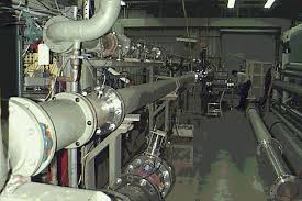
Internal flows through pipes, elbows, tees, valves, etc, as in this oil refinery, are found in nearly every industry. Osborne Reynolds was the first scientist who had distinguished the type of flow by using a simple apparatus in 1883. |
Figure 1: Laminar, Transitional and Turbulent Flows
|
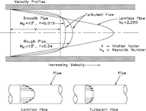
Figure 2: Velocity Profiles of Laminar and Turbulent Flows
|
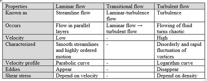
Table 1: Properties of Laminar, Transitional and Turbulent Flows
Video 1: Various types of flows in a pipe
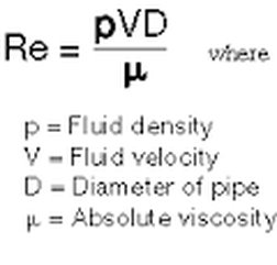
2. Reynolds Number, Re
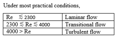
Table 2: Precise Values of Reynolds Numbers
|
|
Video 2: Reynolds Number
3. Laminar and Turbulent Flow
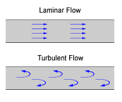
Figure 3: Laminar and Turbulent Flow
|
(a) Laminar Flow:
- Re < 2300 - Path line each particles are parallel - Low velocity - Viscosity plays a significant part - Velocity profile: Parabolic Curve |
(b) Turbulent Flow:
- Re > 4000 - Path line each particles are irregular - High velocity - Inertia plays a significant part - Velocity profile: Logarithm Curve |
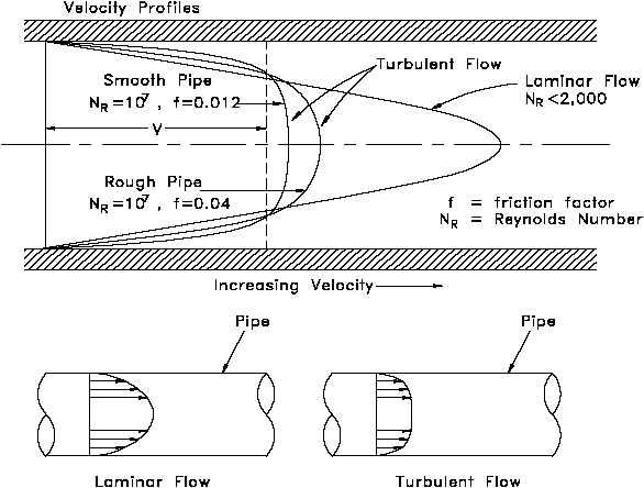
Figure 4: Velocity Profiles of Laminar and Turbulent Flows
4. Friction in Pipe
Energy Head Loss
Major Head Loss, hf : Friction occur along the pipe.
Minor Head Loss, hm : Friction occur when there is a flow disruption along the pipe (entrance).
Major Head Loss, hf : Friction occur along the pipe.
Minor Head Loss, hm : Friction occur when there is a flow disruption along the pipe (entrance).
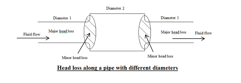
Figure 5: Head Loss along a pipe with different diameters
|
Factors that affect head loss
|
|
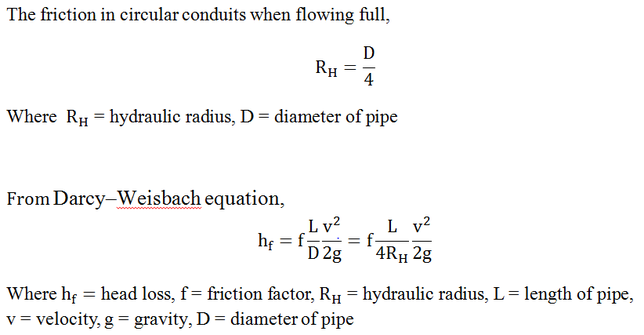
Friction in Circular Conduits pipe
Friction in Non-circular Conduits pipe
Formula Hagen-Poiseuille
- This Formula used for Laminar flow.
- This Formula used for Laminar flow.
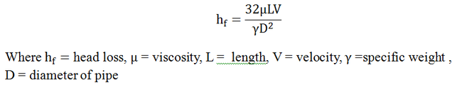
- Equation shows that in Laminar flow, the loss of head is proportional to the first power of velocity.
- In Laminar, the friction is independent of the roughness of the pipe but depends on viscosity and density.
- In Laminar, the friction is independent of the roughness of the pipe but depends on viscosity and density.
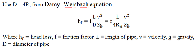
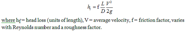
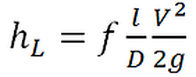
Formula Darcy-Weisbach
- In Laminar flow, the head loss varies as V and inversely as D2.
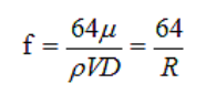
Indicating that the friction factor is proportional to viscosity and inversely proportional to the velocity, pipe diameter, and fluid density under Laminar flow conditions. The friction factor is independent of pipe roughness in Laminar flow because the disturbances caused by surface roughness are quickly damped by viscosity.
Friction factor, f
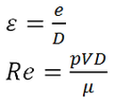
- Friction factor depends on Reynolds No (R) and relative roughness (Ԑ = e/D) where e is a pipe roughness and D is a diameter of pipe.
- Friction factor depends on Reynolds No (R) and relative roughness (Ԑ = e/D) where e is a pipe roughness and D is a diameter of pipe.
Friction factor in turbulent flow
In turbulent flow, relative roughness contribute a significant part besides Reynolds No. Friction factor can be calculated by:
In turbulent flow, relative roughness contribute a significant part besides Reynolds No. Friction factor can be calculated by:
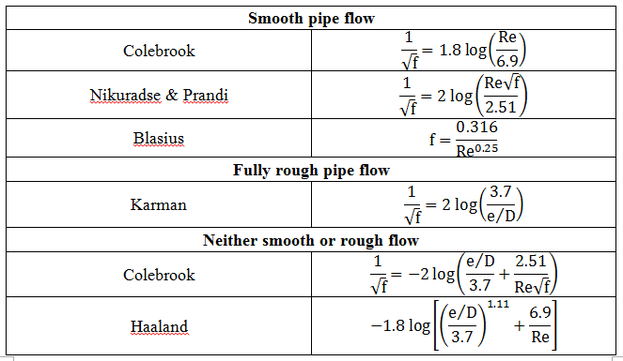
Table 3: To calculate friction factor
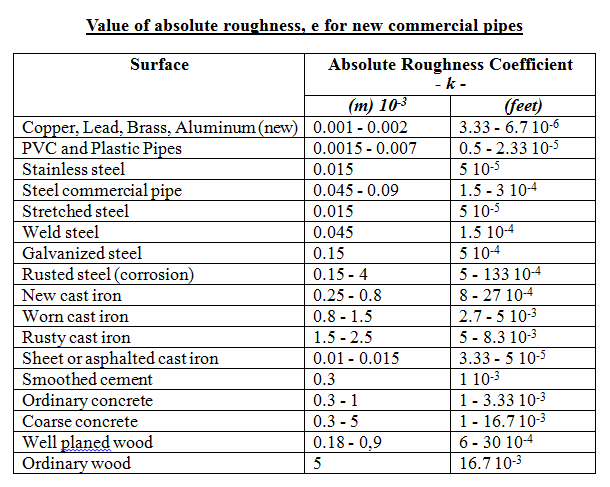
Table 4: Value of absolute roughness, e for new commercial pipes
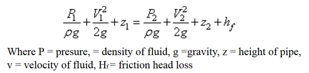
5. Bernoulli Equation
Bernoulli Equation is an approximate relation between pressure, velocity, and elevation, and is valid in regions of steady, incompressible flow where net frictional forces are negligible. Problems related to real fluids can be analyzed with the help of a modified form of Bernoulli equation as:
6. Pipe Problems
Three types of pipe problems:
(a) Determine hf, when L, D and Q are given.
(b) Determine Q, when L, D and hf are given.
(c) Determine D, when L, Q and hf are given.
(a) Determine hf, when L, D and Q are given.
(b) Determine Q, when L, D and hf are given.
(c) Determine D, when L, Q and hf are given.
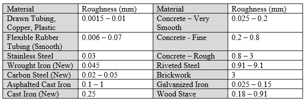
Table 5: Materials and its roughness
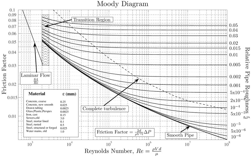
Figure 6: Moody Chart
|
(a) Determine hf
- Find e from Table 5. - Use Re and Ԑ to obtain f from Moody Chart, then calculate head loss. - Use Darcy-Weisbach equation. |
|
|
|
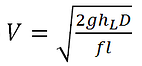
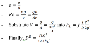
(b) Determine Q
- Find e from Table 5. - Assume value of f ≥ 0.020. - Substitute f into the equation below to find V. |

- Substitute V into the equation below to find Re.
|
- Use Re and Ԑ to find f. If f is different, substitute into V follow by Re until f is constant.
- Value of f is found. Substitute f into the equation below again and then Q = VA. |

|

|
|
|
(c) Determine D
- Find e from Table 5. |
|
- Assume value of f ≥ 0.020.
- Substitute f into D and substitute D into Re, use Re and Ԑ to find f, - This step is repeated until the value of f is constant. - When the value of f is found and value of D is determined. |
7. Minor Losses in Pipe
Minor losses mean losses due to local disturbances of the flow in conduit. Minor losses can be expressed as:
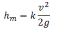
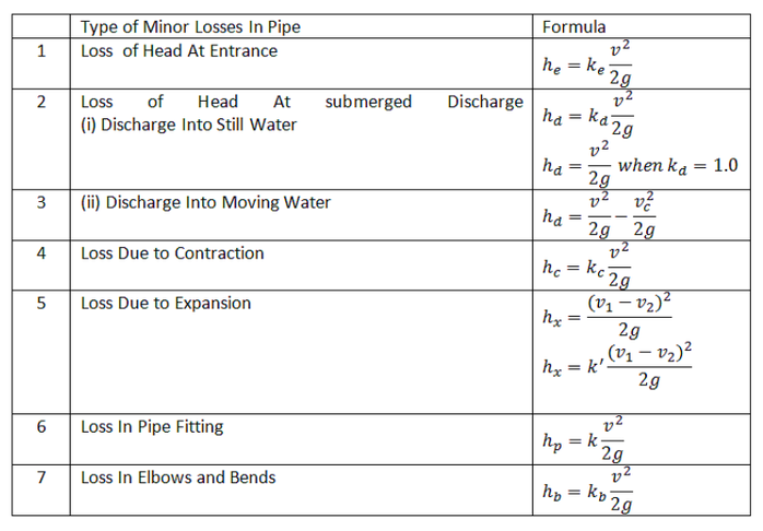
Table 6: Type of Minor Losses in Pipe and their formulas
Loss of head at Entrance
- The streamlines continue to converge and with maximum velocity and minimum pressure exist.
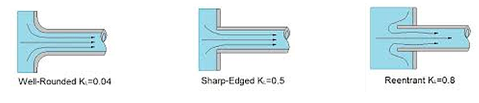
Figure 7: Head Loss at Entrance
Loss of Heat at Submerged Discharge
|
(a) Discharge into Still Water
- Discharge from the end of the pipe into closed tank or reservoir - Velocity is large, kinetic energy is dissipated |
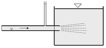
Figure 8: Discharge into Still Water
|
|
(b) Discharge into Moving Water
- Discharged enter a body of water moving away in a channel - Discharge loss is equal to the difference between the discharged and ultimate velocity heads |
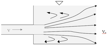
Figure 9: Discharge into Moving Water
|
|
Loss due to Contraction
- There is a drop in pressure due to the increase in velocity - Loss of energy in turbulence - To reduce the loss of head, it can be changing one diameter to the other with smoothly curved transition (with or with frustum of a cone with angle 20-40) |
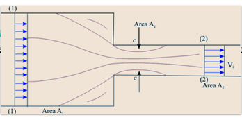
Figure 10: Loss due to Contraction
|
|
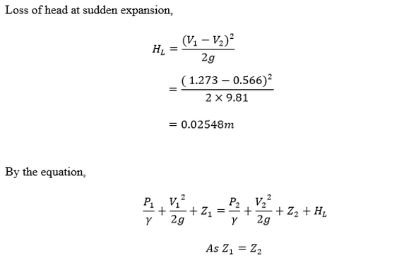
Loss due to Expansion
- There is a rise of pressure due to the decrease in velocity - Excessive turbulence - Eddy currents are created - To reduce the head loss, a diffuser can be used - This will results gradual expansion |
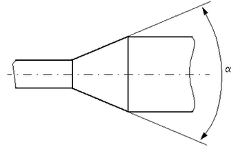
Figure 11: A cone with angle
|
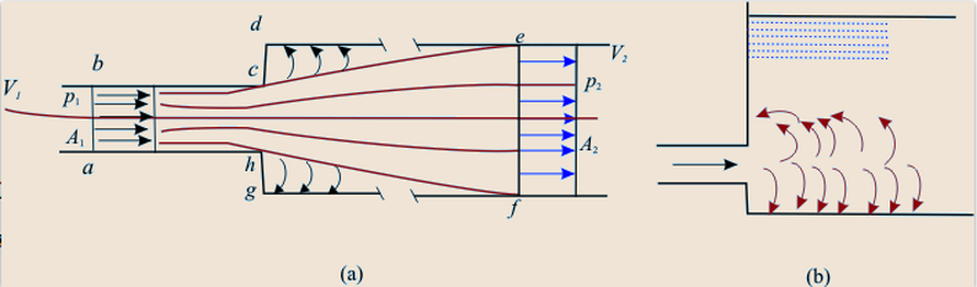
Figure 12: Eddy currents are created
Loss in Pipe Fitting
- The loss coefficient k depends on the type of fitting
- The loss coefficient k depends on the type of fitting
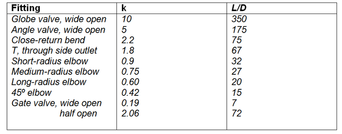
Table 7: Type of fitting
|
Loss in Elbows and Bends
- There is an increase in pressure (outer wall) and a decrease in pressure (inner wall) - Most of the head loss due to a sharp may be eliminated by using a vanned elbow. - The vanes impede the formation of the secondary flows. |
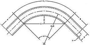
Figure 13: Loss in Elbows and Bends
|
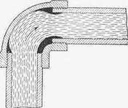
Figure 14: Loss in Elbows and Bends
|
8. Examples and Calculations
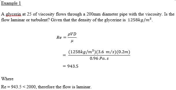
Example 1:
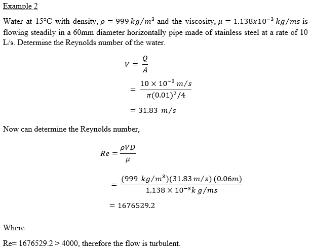
Example 2:
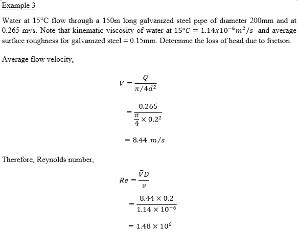
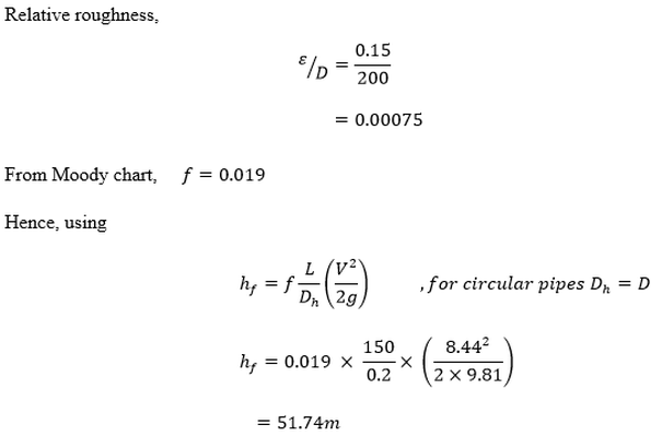
Example 3:
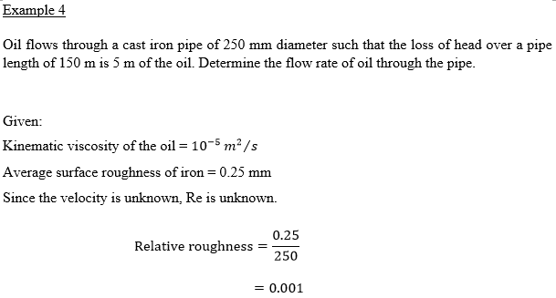
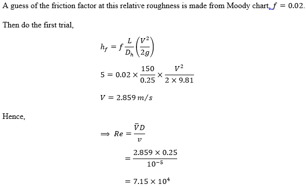
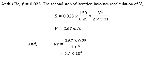
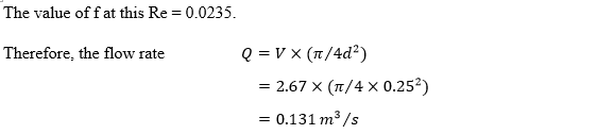
Example 4:
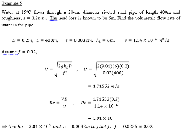
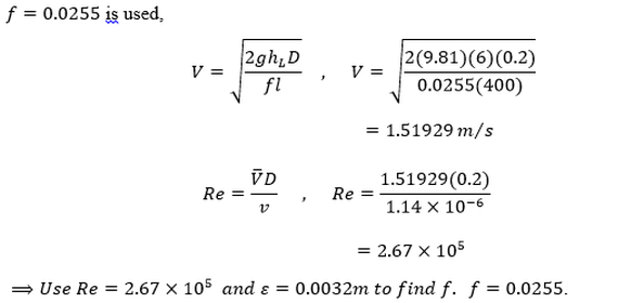
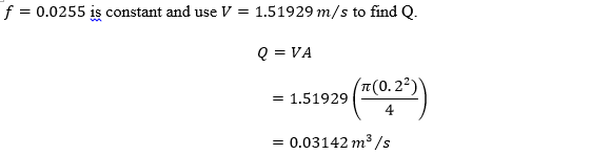
Example 5:
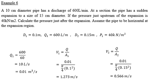
Example 6:
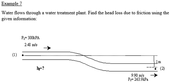
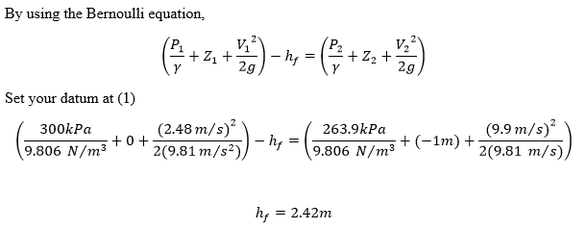
Example 7:
9. Conclusion
In this topic we discussed the properties of a
moving fluid and what happens to objects that travel in a fluid. Two
types of fluid flow will be considered: laminar flow and turbulent
flow. In laminar flow the particles in the fluid follow streamlines, and
the motion of particles in the fluid is predictable. If the flow rate is
very large, or if objects obstruct the flow, the fluid starts to swirl in an
erratic motion. No longer can one predict the exact path a particle on
the fluid will follow. This region of constantly changing flow lines is
said to consist of turbulent flow. Next, the Bernoulli equation is very
useful, partly because it is very simple to use and partly because it can give
great insight into the balance between pressure, velocity and elevation. When a fluid is flowing through a pipe, the fluid
experiences some resistance due
to which some of the energy of the fluid is lost. This loss of energy is
classified as major
energy losses and minor energy losses. As a result, through this topic,
we can do all the pipe flow analysis and determine the losses in pipe.
10. Appendix (Minutes 1 & 2)
Minutes of group meeting 1:
Minutes of group meeting 2:
11. References
Yunus A. Cengel (2010), Fluid Mechanics Fundamentals and applications, McGraw-Hill Education (Asia)
Merle C. Potter (2009), Fluid Mechanics Demystified (A Self-teaching Guide), The McGraw-Hill Companies
J.F. Douglas & R. D. Matthews (1996), Fluid Mechanics (Volume 1), Longman Group Limited 1996
Various types of flows in a pipe, https://youtu.be/6OzAx1bPGD4
Reynolds Number, https://youtu.be/kmjFdBxbV08